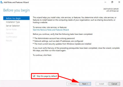
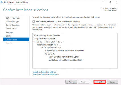
KB ID 0001256 Dtd 09/11/16
Problem
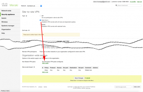
This was asked as a question on Experts Exchange this week, and it got my interest. A quick search turned up a bunch of posts that said, yes this is possible, and you deploy it with FreeRADIUS and it works great. The problem was, a lot of the information is a little out of date, and some of it is 'wrong enough' to make the non-technical types give up. But I persevered, and got it to work.
![AnyConnect-GoogleAuth-Radius]()
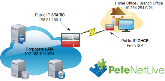
Disclaimer: This is not an exercise in deploying AnyConnect, I've got that covered to death all over the website, use the search function above, or simply go to the following article;
Cisco ASA 5500 AnyConnect Setup From Command Line
So before proceeding I'll assume you have AnyConnect setup, and you can connect with a local username.
Disclaimer 2: Please don't email me with questions like, "Can I take this and integrate it with Active Directory, eDirectory" etc. Or "I'm trying to get this to work with 'insert name of some Linux distro" and I'm getting an error.
Prerequisite: You will need to have the Google-Authenticator app on a device, (probably an IOS or Android phone), and have that running, and ready to accept a new identity/account.
Solution
Setup FreeRADIUS
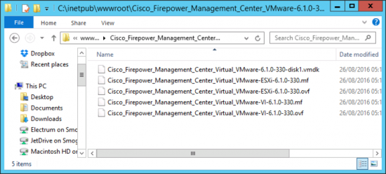
I'm not a Linux guru, I just downloaded the latest version of Ubuntu Server (16.04.1 at time of writing). and deployed it as an ESX host.
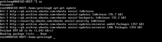
Non Linux Types Note: A lot of the commands below require you to either be logged on as root, or 'su' to root, (if that's not an option, you will need to prefix the commands with 'sudo'.
Ubuntu Enable Root Account: I quickly learned that these days the root account is disabled, (for sensible reasons). However because of the way FreeRADIUS works, it needs to run under the root account.
sudo passwd root
ENTER AND CONFIRM PASSWORD
sudo passwd -u root
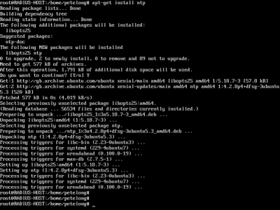
Ubuntu: Install Prerequisites: We need to get all current updates, then install NTP, (because the authenticator keys are time specific). Then there are some tools that we will need to install the Google Authenticator software.
apt-get update
apt-get install autotools-dev
apt-get install autoconf
apt-get install libtool
apt-get install ntp
apt-get install build-essential libpam0g-dev freeradius git libqrencode3
![Update Ubuntu]()
![Install NTP Ubuntu]()
Install Google Authenticator: This is quite cool, (if like me you don't do a lot of Linux). We need to connect to a folder on a web server, then move into that 'Directory' and install the software.
cd ~
git clone https://github.com/google/google-authenticator.git
cd google-authenticator/libpam/
./bootstrap.sh
./configure
make
make install
Configuring FreeRADIUS and Google-Authenticator
Ubuntu has nano installed by default thats what I'm going to use, if you're a sandal wearing 'vi' user, then feel free to use that instead.
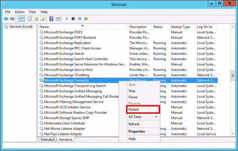
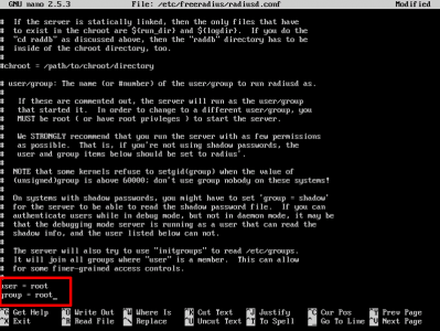
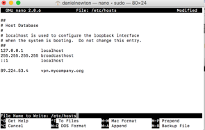
First we are going to change FreeRADIUS, so it runs under the 'root' account.
nano /etc/freeradius/radiusd.conf
At the bottom of the file, change the user and group from freerad to root, save the file and exit.
Like so:
![Allow Root FreeRadius]()
Next we are going to create a group called radius-disabled, then if you need to deny a user access, you can simply make them a member of this group.
Then configure FreeRADIUS to reject members of that group.
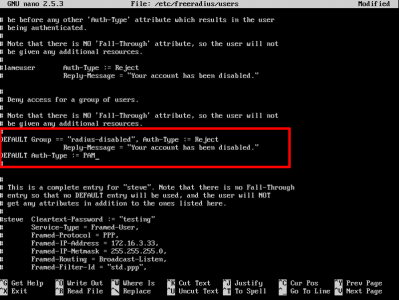
nano /etc/freeradius/users
Locate the lines indicated below;
![RADIUS Reject Users]()
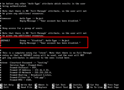
Change and un-comment them, to add the following text;
DEFAULT Group == "radius-disabled", Auth-Type := Reject
        Reply-Message = "Your account has been disabled."
DEFAULT Auth-Type := PAM
So it looks like below, then save and exit the file;
![RADIUS Reject Users PAM]()
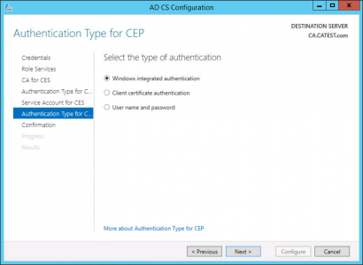
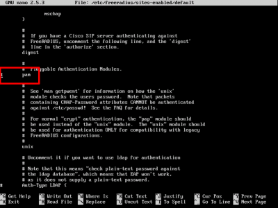
Enable Pluggable Authentication Mode (PAM): Edit the following file;
nano /etc/freeradius/sites-enabled/default
Locate the line with 'pam' in it and uncomment it (remove the hash/pound sign), like so
Before;
![Free RADIUS Enable PAM]()
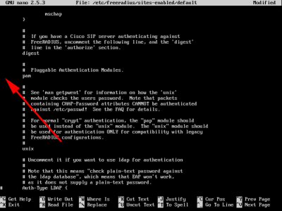
After;
![Free RADIUS Enable PAM config]()
Exit and save the changes.
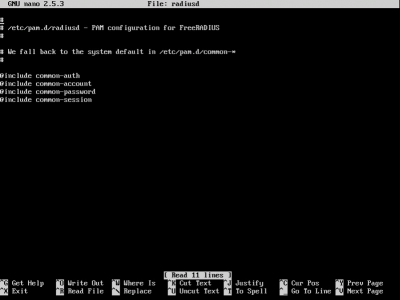
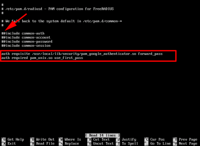
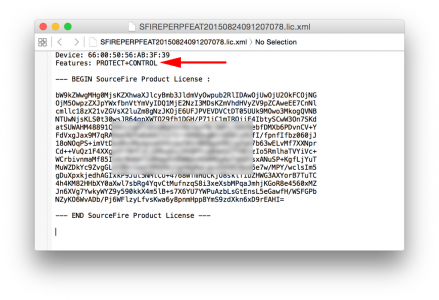
Configure FreeRADIUS to use Google Authenticator: Edit the following file;
Locate all the lines that start with an '@' symbol and comment them out, (prefix them with a "#"), then paste the following text onto the end of the file;
auth requisite /usr/local/lib/security/pam_google_authenticator.so forward_pass
auth required pam_unix.so use_first_pass
Before;
![RADIUS config file]()
After;
![RADIUS Two Factor]()
Testing Google-Authenticator and FreeRADIUS
The easiest way to do this is setup a test user, then create a password for them, then assign a Google-Authenticator Code to that user, on your Linux server;
adduser tommytester
ENTER AND CONFIRM PASSWORD
su tommytester
ENTER THE PASSWORD
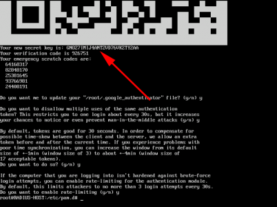
google-authenticator
Now you can either scan the QR code into the Google Authenticator app on your phone, or type in the 'secret-key'.
![RADIUS Secret Key]()
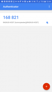
Once done, you should be looking at a 6 digit number, that changes every 30 seconds;
![Google Authenticator App]()
Test Authentication on the FreeRADIUS Server first! To do that issue the following command;
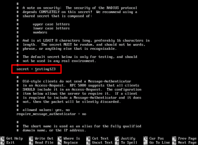
radtest tommytester password456743 localhost 18120 testing123
Note: the password for tommytester is 'password' and the 6 digit code is added to the end of it, the testing123 value is set within FreeRadius in the /etc/freeradius/clients.conf file.
![RADIUS Secret Key]()
Successful Authentication
tommytester@RADIUS-HOST:/home/petelong$ radtest tommytester password302971 localhost 18120 testing123
Sending Access-Request of id 165 to 127.0.0.1 port 1812
 User-Name = "tommytester"
 User-Password = "password302971"
 NAS-IP-Address = 192.168.110.85
 NAS-Port = 18120
 Message-Authenticator = 0x00000000000000000000000000000000
rad_recv: Access-Accept packet from host 127.0.0.1 port 1812, id=165, length=20
tommytester@RADIUS-HOST:/home/petelong$
Unsuccessful Authentication
tommytester@RADIUS-HOST:/home/petelong$ radtest tommytester password302973 localhost 18120 testing123
Sending Access-Request of id 36 to 127.0.0.1 port 1812
 User-Name = "tommytester"
 User-Password = "password302973"
 NAS-IP-Address = 192.168.110.85
 NAS-Port = 18120
 Message-Authenticator = 0x00000000000000000000000000000000
rad_recv: Access-Reject packet from host 127.0.0.1 port 1812, id=36, length=20
tommytester@RADIUS-HOST:/home/petelong$
Troubleshooting: If there's a problem, make sure that the time on the FreeRADIUS server is correct, (is NTP getting blocked at the firewall?) Then what I do is, SSH into the server from another session, and enable debugging, then back at the console test authentication again, then you can see the debugging output on the other screen, which will point you in the right direction.
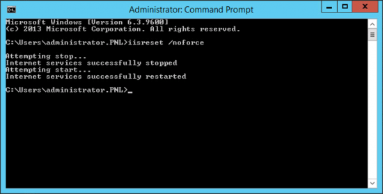
To enable debugging;
service freeradius stop
freeradius -XXX
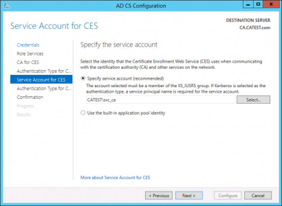
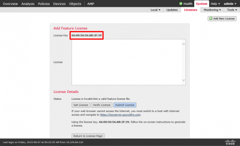
Add the Cisco ASA Firewall as a RADIUS Client: You need to add the firewall as a 'client' before it can authenticate. Edit the following file;
nano /etc/freeradius/clients.conf
Add the following test to the end of the file, (cisco123 is the shared secret we will enter on the ASA later);
client 192.168.110.1 {
 secret = cisco123
 shortname = CiscoASA
 nastype = cisco
}
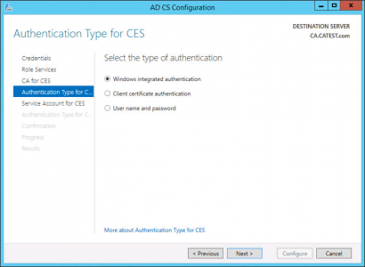
Configure Cisco ASA for FreeRADIUS Authentication
On the ASA you create an AAA group, set its authentication type to RADIUS, then add the FreeRADIUS server as a host, specify the secret key you used above. REMEMBER you need to specify the ports or authentication will fail, (you get a no response error).
aaa-server PNL-RADIUS protocol radius
aaa-server PNL-RADIUS (inside) host 192.168.110.85
 authentication-port 1812
 accounting-port 1813
 key cisco123
 radius-common-pw cisco123
 exit
The ASA also need to have the correct time for authentication to work, I've covered that elsewhere, run through the following article;
Cisco ASA – Configuring for NTP
Change AnyConnect AAA Authentication Method: With nothing set, your AnyConnect is probably using its LOCAL database of usernames and passwords, we now need to change it to use the RADIUS host we just setup. You do that in the AnyConnect's 'tunnel-group general-attribures' section. Issue a show run tun command, to see the tunnel groups listed.
Petes-ASA# show run tun
tunnel-group ANYCONNECT-PROFILE type remote-access
tunnel-group ANYCONNECT-PROFILE general-attributes
 address-pool ANYCONNECT-POOL
 default-group-policy GroupPolicy_ANYCONNECT-PROFILE
tunnel-group ANYCONNECT-PROFILE webvpn-attributes
 group-alias ANYCONNECT-PROFILE enable
Then add your RADIUS GROUP as the authentication server.
Petes-ASA# tunnel-group ANYCONNECT-PROFILE general-attributes
Petes-ASA(config-tunnel-general)# authentication-server-group PNL-RADIUS
Test RADIUS Authentication on the Cisco ASA First: I've covered this in the past see the following article;
Cisco – Testing AAA Authentication (Cisco ASA and IOS)
Remember that the password will be the user password, followed by the 6 digit number displayed on the authenticator.
Petes-ASA# test aaa-server authentication PNL-RADIUS host 192.168.110.85 username tommytester password password125689
INFO: Attempting Authentication test to IP address <192.168.110.85> (timeout: 12 seconds)
INFO: Authentication Successful
Petes-ASA#
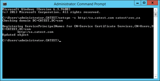
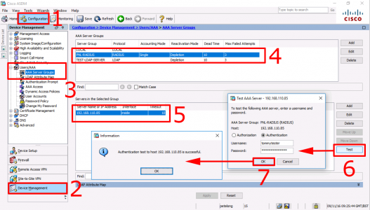
Or. if you prefer to use the ASDM;
![Test AAA 2 Factor Cisco ASA]()
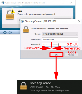
Finally you can test authentication from your remote AnyConnect client.
![AnyConnect and Google Authenticator]()
Related Articles, References, Credits, or External Links
NA